
How Does Chainsaw Clutch Work: Mechanics and Troubleshooting Guide for 2026
Learn how does chainsaw clutch work, from centrifugal shoe engagement to drum maintenance and troubleshooting, updated for October 2026.
 By Andrew McKean
Updated October 2, 2026
By Andrew McKean
Updated October 2, 2026

Every woodcutter who starts a two-stroke powerhead notices that the cutting chain remains motionless while the engine settles into a steady idle. This critical separation of engine rotation from the drive sprocket happens because of a mechanical centrifugal assembly located beneath the side cover. Understanding how does chainsaw clutch work allows operators to maintain proper cutting performance, troubleshoot engine bogging, and prevent premature wear on expensive drive components. Centrifugal force drives the entire mechanism, expanding internal weighted shoes against a surrounding steel drum as the throttle triggers higher engine revolutions.
When an operator squeezes the throttle latch, the rising rotational speed overcomes calibrated spring tension, instantly locking the powerhead to the cutting chain. Unlike simpler timber equipment such as dedicated pruning saws for gardeners that rely entirely on direct manual strokes, a powered chainsaw requires this automatic slip joint to prevent engine stalling whenever cutters bind in dense grain. Proper clutch engagement ensures safe wood bucking, smooth power transfer through seasoned hardwood, and immediate disconnection whenever the engine drops back down to idle speed. Keeping this mechanical interface clean and correctly lubricated protects both the crankshaft bearings and the guide bar.
| Award | Product | TGH Score About TGH ScoreThe TGH Score is our own rating from 0 to 10, based on performance, design and build, ease of use, and value. It reflects independent research and is never influenced by manufacturers, retailers, or affiliate commissions. Learn more › | |
|---|---|---|---|
| Best Overall |
Adefol 502541603 Chainsaw Clutch Removal Tool
|
9.2/10 | Buy |
| Best Budget |
 Bopurtotly 530031116 Chainsaw Clutch Removal Tool
|
9.1/10 | Buy |
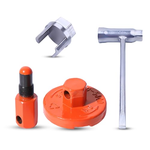 Atunee Piston Stop Clutch Flywheel Disassembly
|
8.9/10 | Buy |
The Mechanical Principles Behind Chainsaw Clutch Operation
A chainsaw clutch operates as an automatic centrifugal coupling that bridges the high-speed crankshaft of the powerhead to the cutting assembly. At idle speeds between 2,700 and 3,300 revolutions per minute, the clutch keeps the cutting chain completely stationary to ensure safe handling on the ground. Once the operator depresses the throttle to accelerate the engine toward its operating range above 3,800 revolutions per minute, centrifugal force drives weighted clutch shoes outward into contact with the clutch drum. This friction contact locks the drum and crankshaft together, driving the sprocket and saw chain through the cut with full engine torque.
Centrifugal Force and Clutch Component Architecture
The internal anatomy of a typical chainsaw clutch consists of three primary components: the central clutch hub, weighted friction shoes, and retention springs. The central hub threads directly onto the end of the engine crankshaft, spinning in unison with the piston strokes. Attached to or resting against this hub are two or three curved metal shoes that expand outward along guide pins or sliding tracks. Calibrated steel tension springs hold these shoes inward toward the center hub, counteracting low rotational forces while the engine idles.
As engine revolutions increase, the rotational mass of the clutch shoes generates outward kinetic energy known as centrifugal force. This outward force scales exponentially with rotational velocity until it exceeds the mechanical resistance of the retention springs. Once this threshold is crossed, the outer friction faces of the shoes press firmly against the interior circumference of the surrounding clutch drum. The resulting friction causes the drum to spin at the same rate as the crankshaft, transferring mechanical horsepower directly to the drive sprocket.
The outer clutch drum spins on an independent needle cage bearing seated over the crankshaft snout. This needle bearing allows the drum to remain stationary when the engine idles or when the chain brake engages during active operation. Because the drum floats freely on this bearing during low-RPM idling, proper lubrication with heat-resistant grease is essential to prevent galling or scoring on the crankshaft journal. If this bearing dries out or seizes from debris, the drum will drag against the crankshaft, causing the chain to creep dangerously at idle.
Inboard Versus Outboard Clutch Configurations
Chainsaw manufacturers configure powerheads with either an inboard or outboard clutch layout, each offering distinct mechanical tradeoffs. An inboard clutch places the clutch assembly deep inside the chassis against the crankcase, positioning the drive sprocket and guide bar on the outside. This design provides immediate access to the drive sprocket and chain tensioner studs whenever the side clutch cover is removed. Forestry workers frequently prefer inboard setups because swapping worn guide bars or thrown chains requires no specialized clutch removal tools.
An outboard clutch positions the drive sprocket deep against the crankcase, placing the weighted clutch assembly on the very outside under the side cover. Many popular residential and rancher powerheads utilize this configuration because it allows the powerhead chassis to remain narrow and compact. An outboard design also positions the clutch drum closer to the side-mounted chain brake band, providing direct mechanical leverage during emergency stops. However, servicing the drive sprocket or replacing a worn rim requires complete removal of the clutch assembly using specialized tools.
When working on outboard setups, mechanics rely on dedicated removal tools like the Adefol 502541603 Chainsaw Clutch Removal Tool or the Bopurtotly 530031116 Chainsaw Clutch Removal Tool to engage the clutch hub pins without damaging the shoes. These multi-prong spanners mate with matching recesses in the clutch hub, enabling safe torque application with a standard ratchet or socket wrench. Without a correctly fitting tool, attempting to hammer or chisel a clutch off the crankshaft can easily bend the crankshaft or crack the magnesium powerhead case. Investing in designated removal hardware ensures safe maintenance without ruining critical engine components.
Drive Sprocket Mechanics: Spur Versus Floating Rim Systems
The clutch drum directly transfers engine rotation to the saw chain through one of two drive sprocket styles: a fixed spur sprocket or a floating rim sprocket. Spur sprockets feature star-shaped teeth welded permanently to the outer bell or base of the clutch drum. While economical and common on consumer saws, spur teeth wear down quickly from abrasive sawdust and chain grit. Once the tooth channels wear deeper than 0.020 inches, the operator must replace the entire clutch drum assembly to restore proper chain pitch alignment.
Floating rim sprockets utilize a splined clutch drum hub that accepts an independent, replaceable circular rim. The splined interface allows the floating rim to shift slightly side-to-side, naturally aligning the chain drive links with the guide bar groove during heavy cutting loads. This self-aligning capability reduces lateral wear on both the chain drive tangs and the entry rails of the guide bar. When the rim teeth eventually wear out, the operator simply slides off a retention clip and installs an inexpensive new rim without discarding the clutch drum.
Matching the drive sprocket pitch precisely to the cutting chain is critical for safe and smooth timber bucking. Common pitch designations include 3/8-inch low profile, .325-inch, and standard 3/8-inch configurations. Running a .325-inch chain on a 3/8-inch spur sprocket causes extreme tooth peening, severe chatter, and catastrophic drive link fracture. Checking the stamped markings on your replacement rim or drum prevents dangerous drive mismatches that can ruin the entire cutting system.
Safety Dynamics and Chain Brake Interplay
The centrifugal clutch plays a primary safety role by integrating seamlessly with the chainsaw inertia chain brake system. A wide, spring-loaded steel brake band wraps directly around the exterior circumference of the smooth clutch drum. When a kickback event drives the front handguard forward, the tripping mechanism releases a heavy spring that instantly clamps the brake band around the spinning drum. This stopping action halts drum rotation and freezes the saw chain in a fraction of a second, complying with strict ANSI B175.1 safety standards.
Because the clutch drum is separate from the internal crankshaft hub, the engine does not immediately stall when the chain brake fires at operating speed. Instead, the clutch shoes slip along the stationary inner wall of the clamped drum, absorbing kinetic energy while the operator releases the throttle lever. This controlled slippage prevents catastrophic mechanical shock from shearing the crankshaft key, snapping connecting rods, or cracking the engine flywheel. The centrifugal design acts as a sacrificial mechanical fuse that saves the powerhead from catastrophic internal destruction.
Operators must exercise extreme caution never to accelerate the powerhead while the chain brake remains locked. Applying wide-open throttle against an engaged brake band generates severe friction heat within seconds. This intense heat turns the steel clutch drum blue, melts adjacent plastic crankcase components, and anneals the clutch retention springs. Overheated clutch springs lose their calibrated elasticity, causing the shoes to drag continuously and spin the chain even at engine idle.
Diagnosing Common Clutch Symptoms and Mechanical Faults
A frequent operational defect is a cutting chain that spins continuously while the powerhead idles on the ground. This condition represents a severe hazard under OSHA logging safety standards and indicates that the clutch is failing to disengage. In many instances, one or more retention springs have stretched, cracked, or unhooked from their mounting eyelets. Alternatively, fine sawdust mixed with sticky bar oil can pack behind the clutch shoes, physically jamming them in the extended position against the drum.
Another common complaint occurs when the engine revs freely to high RPM, but the cutting chain bogs down and halts inside the wood kerf. This slippage points to severely worn friction pads on the clutch shoes or a glazed, polished surface inside the clutch drum. Chain oil leaks or grease contamination inside the drum will also cause total loss of friction, allowing the shoes to spin without turning the chain. Cleaning the drum with non-chlorinated brake cleaner and scuffing the contact surfaces with medium emery cloth often restores necessary friction.
Loud screeching, metallic rattling, or visible wobble around the clutch drum points directly to needle cage bearing failure. When the needle rollers wear unevenly or lose their lubricating grease, the drum tilts out of alignment with the crankshaft axis. This misalignment produces excessive vibration, damages the oil pump drive gear, and causes uneven contact between the clutch shoes and drum. Inspecting the needle bearing during every sprocket change prevents unexpected failures that can ruin the crankshaft snout.
Step-by-Step Clutch Removal and Bench Servicing
Servicing a chainsaw clutch requires careful mechanical preparation to avoid damaging internal engine components. Begin by turning off the ignition switch, letting the powerhead cool, and removing the spark plug wire from the boot. Remove the top engine cover and unscrew the spark plug using your scrench or standard plug socket. To remove the threaded clutch assembly safely, the crankshaft must be prevented from rotating while torque is applied to the hub.
Locking the crankshaft requires a piston stop, which is included in comprehensive kits like the Atunee Piston Stop Clutch Flywheel Disassembly set. Gently thread the nylon or steel piston stop into the spark plug hole until it bottoms out against the cylinder head threads. Slowly pull the starter rope until the piston crown rises and makes firm contact with the stop, immobilizing the rotating assembly. Never use hard metal punches or screwdriver shanks as improvised piston stops, as they can easily punch a hole through the thin aluminum piston crown.
Every operator must remember that chainsaw clutches almost universally employ a left-hand reverse thread. This design ensures that engine rotation constantly tightens the clutch hub during active timber cutting rather than spinning it loose. To loosen the clutch, turn the removal tool clockwise; to tighten it back onto the crankshaft, turn counterclockwise. Most clutch hubs feature a stamped arrow labeled OFF indicating the required clockwise loosening rotation.
Mate your dedicated clutch removal tool with the hub, engage your breaker bar or ratchet, and turn clockwise with firm, steady pressure. Once the initial thread friction breaks, spin the clutch assembly off by hand and set it on a clean shop rag. Slide off the clutch drum, retrieve the needle cage bearing, and inspect the plastic oil pump drive gear positioned behind the assembly. Clean all components thoroughly using solvent to remove packed sawdust, wood resin, and hardened bar lubricant.
Apply a modest coating of high-temperature lithium or wheel bearing grease to the needle cage bearing before sliding it back over the crankshaft journal. Never allow any grease, motor oil, or bar lubricant to touch the friction shoes or the inner braking surface of the clutch drum. Reinstall the drum, thread the clutch hub counterclockwise onto the shaft, and torque it snugly against the crank shoulder. The first high-throttle cutting pass will naturally complete final operational tightening of the reverse-threaded hub.
Operational Habits That Protect the Drive Assembly
Maintaining proper cutting chain tension directly preserves the life of the clutch shoes and needle bearing. A loose chain slaps violently against the drive sprocket teeth, transmitting harsh shock loads back into the clutch hub and crankshaft. Conversely, an overtightened chain acts like a mechanical brake on the guide bar nose, forcing the clutch shoes to slip continuously under heavy throttle. Operators should always tension the chain so the drive link tangs remain seated in the bar groove while allowing smooth manual movement around the rails with a gloved hand.
Understanding log compression and tension while bucking firewood prevents the guide bar from pinching inside the kerf. When a falling trunk closes the kerf on the bar, the chain halts instantly while the operator often keeps the throttle wide open. This momentary stalling forces the clutch shoes to grind furiously against the stationary drum, generating destructive heat in just a few seconds. Using plastic felling wedges to keep the kerf open protects the cutting gear from needless thermal destruction.
For lighter wood preparation or yard tasks, many operators alternate between powered timber saws and manual hand saws for cutting tree branches to minimize unnecessary clutch wear on small limbs. Similarly, when squaring structural timbers or fence posts, dedicated equipment like electric saws for cutting fence posts can deliver cleaner cuts without exposing a two-stroke clutch to fine construction grit. Selecting the appropriate tool for the job keeps the chainsaw in prime condition for demanding hardwood bucking and tree felling tasks.
Periodic inspection of the clutch drum, springs, and needle bearing ensures your chainsaw operates safely and reliably through every season. Cleaning out accumulated bar oil sludge, monitoring sprocket tooth depth, and replacing fatigued springs prevents sudden chain creep and dangerous cutting delays. Mastering the simple mechanics of centrifugal engagement empowers you to perform timely repairs and maintain optimal cutting torque across all timber cutting projects.
About the author
Andrew McKean is an experienced outdoor journalist and optics specialist with extensive experience evaluating binoculars, spotting scopes, and other outdoor optical equipment. His work combines practical field testing with detailed technical analysis, helping readers understand optical performance, durability, and the features that matter when comparing equipment.